
Welcome to Garys’ Web Page (Updated May 2026)
)
Smith Domain Incorporated


How to make a Simple Solar Tracker
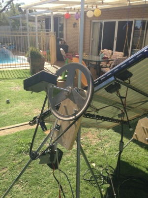
The schematic was in the January 1995 Silicon chip and was almost perfect for what I wanted to do, but after construction, I found that no mater how much rail voltage was supplied, it only gave 7v output to the motor drive, so I had to modify the schematic so that it can take in and give out a rail voltage of up to about 30v. The reason was that I needed a higher motor drive voltage, to drive the 36v actuators that are mainly used for the tracking of satellite dishes, the actuators do actually run OK on 12v, bit slow but OK.
I put a charge circuit for the charging of say a 12v 4Ah battery (Max 1A) to run the actuator facing back to east after the sun has set. The FETS used in this H pattern then it is capable of switching 6 amps. The light duty actuators take 0.5A each, and the heavy duty actuator take 1.5A each.
This is the Bill Of Materials (BOM) for the tracker with JACAR part numbers
DOWNLOAD the pdf files of my Version 15 mods if you have one of my boards
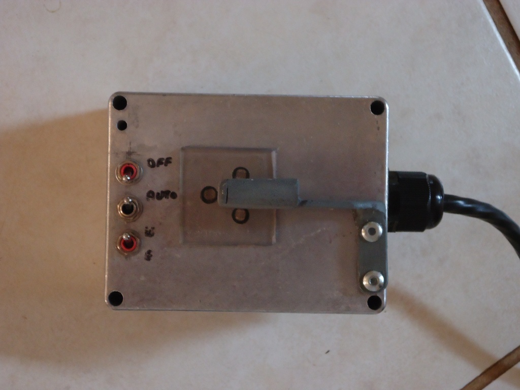
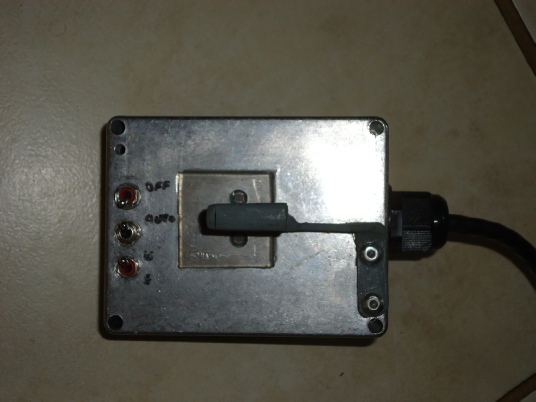
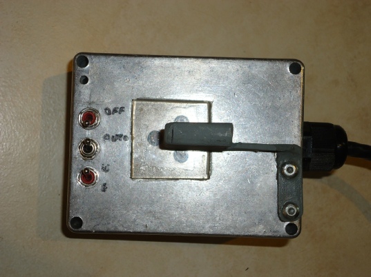
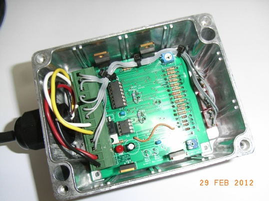
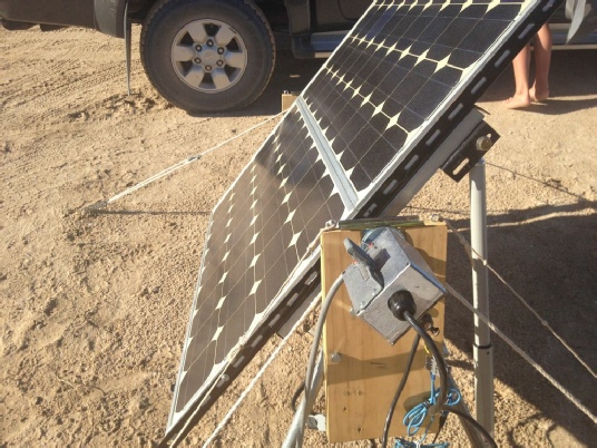
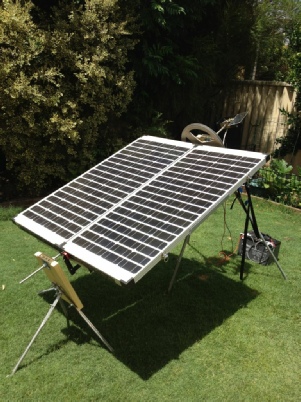
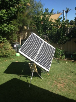
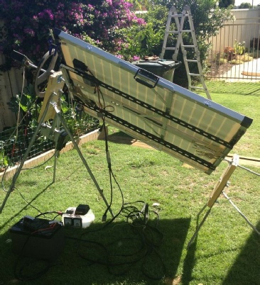
Tracker Finished and Working

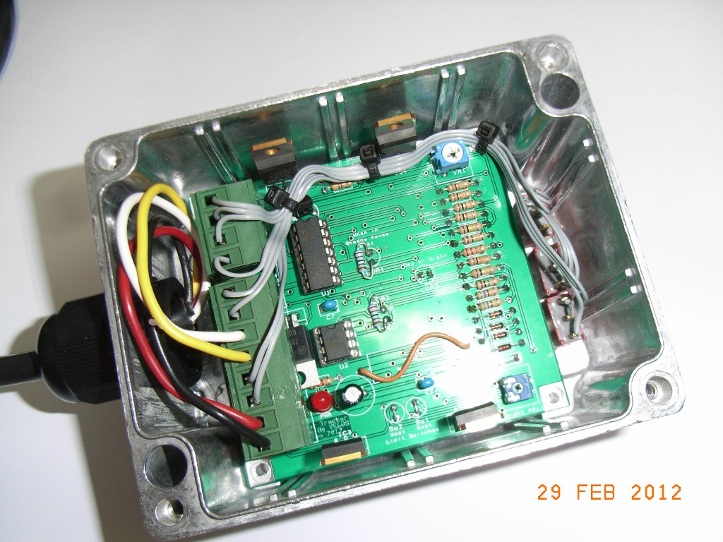
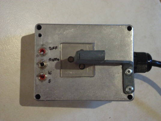
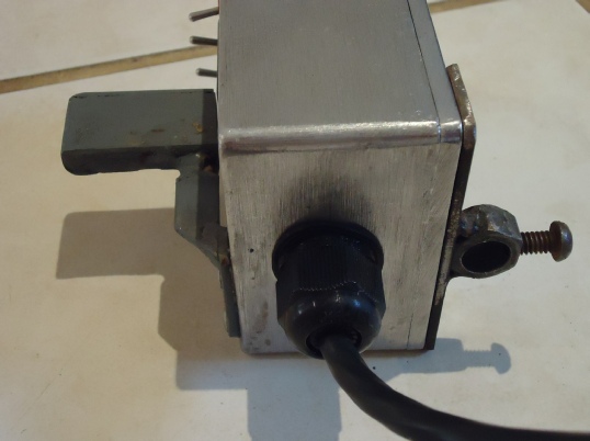
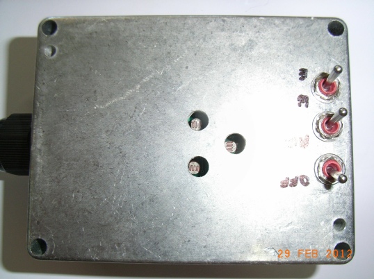
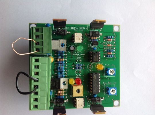
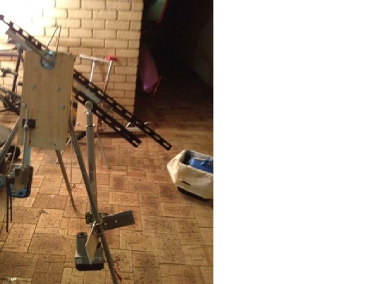
Tracker mounted in the box
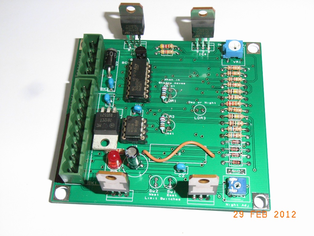
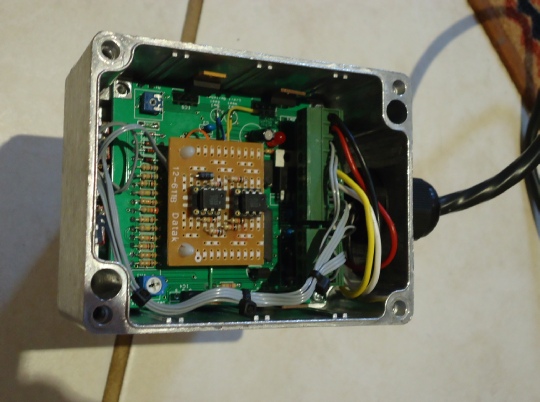
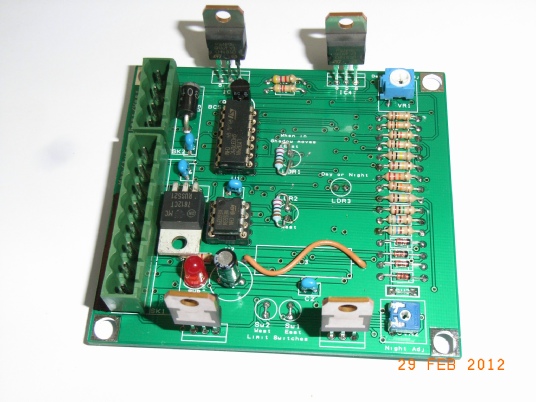
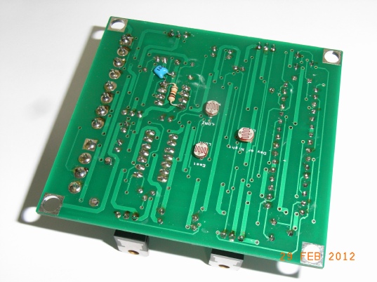
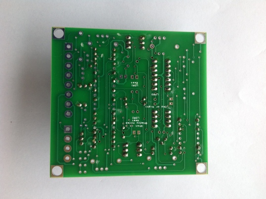
Tracker’s printed circuit board

Download Solar Calculations in Excel,
or go to NOAA, The calculations in the NOAA Sunrise/Sunset and Solar Position are based on equations from Astronomical Algorithms, by Jean Meeus. That is, tells you anything about the SUNS MOVEMENTS.

| An Enjoyable Trip |
| Aviation Events & Links |
| Wagin Airstrip |
| Katanning Weather |
| Katanning Sale Yards |
| 6WA |
| Mothers Memiors |
| Carmans Memiors |
| Amateur Radio |
| opps |
| Other stuff |
| Suns Azimuth Tracker |
| Sun Solar Tracker |
| Suns Elevation Tracker |
| leaf rake |
| windrow rake |
| Fire Lighter |
| Oil Heater |
| Yamaha HS6/8 |
| Power Monitoring |
| Stappleton Station Bores |
| Smithvale UPS |
| Tank Water Level |
| Smith Family Stuff |